This page is at least 13 years old !

This hack is about rewriting the firmware of PLL FM transmitters based on AVR microcontrollers to add more functionalities. They're commonly available on eBay from various sellers and for prices ranging from $40 to $80, depending mostly on the RF output power. If you don't know if a similar transmitter is based on an AVR or not, don't hesitate to ask the seller for a (good) picture of the PCB. They'll certainly accept as there isn't anything secret about the design. Most of the transmitters I came across in that price range are based on AVRs. Those that are able to read audio files from SD cards or USB drives probably host an obscure microcontroler capable of handling those functionalities easily (not supported here !). Presentation video:
 The transmitter I used to test this hack relies on a ATMega48 micro and a BH1415 PLL FM transmitter chip (complete datasheet). The user interface is made of a 3.5 digits display and 2 buttons (normally used to, you guessed it, increment and decrement the frequency). A 3-wire link between the micro and FM modulator chip allows it to configure the frequency and transmission type (mono or stereo). I hooked up my knockoff AVRISP programmer to the convenient 6-way ISP header footprint on the PCB, powered up the transmitter and checked if I could read the device signature. The next step was to see if I could at least do a backup of the original firmware by reading the flash memory contents. Unfortunately, it was locked, so I had no other choice than erasing the AVR and writing everything from scratch. 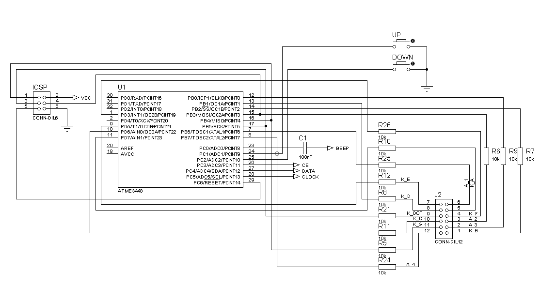
First, I had to know how the AVR was connected to the rest of the circuit. Nothing complicated, it was just a matter of following traces and beeping a few hidden ones. The 7-segment display interface (on port B and D) has obviously been routed to simplify the board layout. The BH1415 interface and button inputs are on port C. Nothing can really go wrong as all the signals for the LEDs of the display go through 1k resistors (twice, in fact), and the BH1415 is immune to bad data.

For the scan functionality I wish to add, I wanted an intermittent tone to be transmitted from the micro so I could hear it and stop scanning without needing an external audio source to generate it. The 100nF C1 cap on PC0 is there for that, it's connected on the other end just before the L (or R) RC filter input going to the BH1415. That way, a square wave signal can easily be "mixed" with the potential audio signal coming from my mp3 player without damaging anything. Speaking of it, talking to the BH1415 is also very easy, it only consists of serially sending a 16bit word. Everything to know is in the last pages of the datasheet: put CE high, put data bit 0, clock, put data bit 1, clock... put CE low. Finished. There's 11 bits for the frequency (in 100kHz steps), one bit to select mono or stereo operation, two bits for the phase comparator setting (had to take a wild guess, it was 00), and two fixed test bits. The "sendBH1415" C function takes care of sending that data.  The 3.5 digits display didn't have a part number and is rather uncommon. I couldn't bother spending 10 minutes searching the datasheet for a similar part so I just probed the pins with my multimeter in diode mode. Nothing extraordinary either: there's common anodes for each digit and unique cathodes for each segment. The B and C segments are inverted for the "1" digit but that doesn't matter as they're either both on or both off. I used the Timer0 overflow interrupt of the ATMega48 to scan through the 4 digits fast enough so that the human eye cannot see that there's only one digit lit at the time (multiplexing that way is used in almost every multi-digit displays, it saves pins and power). Finally, I added the saving of the last used frequency to EEPROM, which is read back when the power is cycled. Be sure to always sanitize read EEPROM values as they can get corrupt with firmware updates and get out of the range you planned your code for. So if you get your hands on the same or a similar transmitter, here you go:
Before flashing the hex file, please make sure that your transmitter is the same as mine, or things could get very glitchy. The source code is heavily commented and changing the #defines to match the schematic of another similar transmitter should be easy if you're used to AVR GCC. |


