This page is at least 13 years old !
The idea came to me during one of my internet breaks during which I wander between stupid videos for fun and to destroy the remains of my brain. I came across a pretty popular video that showed a guy trying one of these training collars for dogs on his neck.
In principle, the idea is almost the same: to associate an unpleasant event with an unpleasant sensation. Except that the event is unpleasant for those who suffer the punishment! To still be interesting apart from the purely masochistic side, I thought it would be fun if these events depended on a quality (agility, speed, memory ...) or the chance of the subject. The best choice to my liking was the video game console! In practice, this gives video games capable of controling these collars to inflict high voltage shocks to players when they lose (or for example, when the opponent wins, there can be many possibilities !).
At first I thought about doing the mod on the NES, because it's still relatively popular today, the game library is quite extensive, and the architecture wasn't too complex for me (although I'm known by some for hating the 6502). I quickly recalled that the NES, in addition to having a crappy processor, was known to have games with an innumerable number of mappers. These chips are used to map the ROMs (memory chips in the cartridges) in banks in order to have "big" games. Since the flash cartridge I made a while back was made on a SLROM circuit, we could only have played the games released on the same circuit, which would have really limited our choices (in addition to having to flash the games with a programmer). The fact that my flash cartridge was not recognized anymore definitely convinced me to change platform. The next "logic" choice for me was the Master System (you know, the one with Alex Kidd embedded ?).
It did not take me more time to take a decision: it will be the Genesis. All the key elements were present: The choice of games, the simplicity of dropping the ROMs on a SD card, and the availability of the hardware in case of an accident (you never know what can go wrong).
Firstly I would like to reassure some. For those who would like to do this mod but who are too protective to touch their Genesis, fear not: No need to modify your console to discover the joys of high voltage, we will only be using the joypads! (Which will still function normally, by the way). We want to command the collars on or off (shock or no shock). For this, we just need a digital output from the console. Knowing a bit about the Genesis already, I knew that this was available on the joypad ports. At first glance, without knowing anything about the console, one might say that the joypad ports are only inputs that correspond to each button. But how does it work with the 11 buttons and the 7 data pins ? (9 really, but 2 are for power). The 7 pins of the ports are actually configurable as inputs or outputs. Typically, games configure them as six inputs and one output. There is an integrated circuit in the joypads that is wired so as to "listen" to this output, and which answers back the status of one out of two groups of buttons. When the game wishes to read the state of all buttons, it will first output a 0 to read the Top, Bottom, Left, Right, B and C buttons, then will set the output to 1 to get the Start and A buttons.
I then thought of using this output to convey additional information to joypads and make them a bit more intelligent so they are able to understand this new information. Initially I was thinking of using a conventional counter circuit, which would count the number of pulses received on SELECT and which would reset to zero when the signal was stable (to avoid counting the pulses 50 / 60 times per second). Since I couldn't find a simple solution to decode the signal and ignore the signal's polarity, I opted for a Atmel ATtiny25 microcontroller. They are small, have 5 I/O pins, operate at 5V, have an internal oscillator, and are inexpensive. They offer everything we need: understanding a defined signal as an input and drive an output to enable or disable the collar. Everything can simply be modified in software. As I doubt some of you don't have AVR programmers, I can help you out on request by email .
We'll connect it to pin 2 of our ATtiny25. We will also give him power, by getting the 5V as shown in red, and ground as indicated in gray. Optionally, you can add a LED after a few hundred ohms resistor on pin 7 of the microcontroller, which may be useful to know if the signal is well received without having a collar to test. Finally, the pin 3 will serve as a control signal for the collar (named SIG).
You can also take advantage of this opportunity to clean the button contacts with alcohol, scrub the conductive membranes with a pencil, and put a few layers of paper behind the disk of the directional pad to harden the touch. For connection to the collar, I used a 3-way male Molex connector (Power + signal), its look isn't great but it's very sturdy and simple to install. I cut 3mm from the edge of the plastic on the bottom of the joypad to place the connector, with the soldering pins bent outward to prevent movement (see picture). The picture shows that the pinout I chose for the connector is as follows, from left to right: +5V, GND, SIG (output signal to the collar). Of course the order of the pins doesn't matter but you must remember it in order to not fry the collar.
The collar I bought on eBay was sold at a surprisingly low price, especially when you know the price tag of the branded ones available in pet supplies shops. Numerous patents such as this one and that one clearly describe how these collars deliver electric shocks. A simple transformer and one or two transistors are used to convert low voltage pulses from the battery to high voltage, low current pulses.
This kind of bulbs can still be found in some old appliances or low end devices as indicators of the presence of a relatively high voltage (hundreds of volts) without the use of resistors and diodes. A LED here would certainly not survive the high voltage pulses, although very short and of low intensity. In contrast, a conventional bulb would also be inappropriate because it would light up with a low voltage and so would be a poor indicator of the proper operation of the collar. As it was impossible to find voltage and current values on eBay and in the user manual ("13V", yeah right !), I had to make some basic measurments to at least know what to expect (if I would suffer greatly or a lot).
I got about 1Mohm per centimeter of skin, so I just took a 5.6Mohms resistor to place between the collar's electrodes, and measured the voltage across it with an oscilloscope. Know that the skin resistance varies greatly depending on its moisture. By wetting my finger and pressing the probe tips as much as possible, the value lowered to about 800kOhms.
If we assume the worst value will be 500V, we will get a 500/5, 6.10e6 = 90μA current value, nothing really dangerous in fact (that doesn't mean it won't hurt!). I also observed the signal on the base pin of the transistor that switches the battery voltage on the transformer's primary, just to see what it looked like. It turns out that the manufacturer of the collar chose 50μs pulses, 300μs apart by bursts of 50, bursts that are spaced 100 ms apart and repeated 30 times (for a total of approximately 3.5 seconds).
We'll just completely bypass the brain of the collar by cutting the connection between the microcontroller and the transistor. On the schematic on the left, you can see that we will only use a small part of the components of the collar, just what's used to provide the high voltage pulses. This means that the microcontroller we will add in the joypads produce needs to produce a control signal similar to the original one. Nothing complicated to do with a few loops and a timer. This will even enable us to have zaps of different lengths !
Connections to the 5V supply will be made on the two large welds from the spring contacts of the battery, while the SIG wire will go on the resistor just before the transistor. Note that the value of this resistance may vary from model to model. Given the short duration of the control pulses, it may be omitted to get voltage peaks a tad higher. As it is likely that the cable will suffer some pulling during the torture session, it is better not to trust the welds and make a knot in the cable before it leaves the housing of the collar. That way, the plastic housing will hold the cable (common practice in low-end hardware where molden knots are too expensive).
For mechanical strength reasons as well, these connectors have a self-locking clip. I added a few inches of heat-shrink sleeve on the connector base, which I filled with hot glue to inflict the effort of pulling the plug to the plastic rather than the welds.
Also note the red LED on the top right.
The microcontroller's code was written in C for AVR-GCC. Here are the available downloads: The code isn't that complicated at all.
All we want to do is to detect a particular signal from the console, and in the case it's detected, provide a control signal to the collar. As written above, we want to detect a special signal that the game will generate and you want to ignore all other signals (in order to avoid false triggering, that wouldn't be fair). We know that normally, the SELECT signal received by the joypad changes state 50 or 60 times per second. There is however a case I didn't speak of, which is when the game is compatible with 6-button joypads. I will not describe how they work here because it doesn't matter much for what we want to do, but be aware that these games can cause up to 8 state changes per frame ! It's also required that the counting of the edges are reset to zero after a period of inactivity on SELECT, so as not to increment the counter each frame. For this, we use the Timer0 Overflow interrupt. The Timer0 is a 8 bit counter which is incremented automatically at short, regular intervals. When its maximum value is reached (255), it will trigger the Overflow Interrupt and will put the edge counter to zero. We will set the Timer0's prescaler to 3, which according to the datasheet, indicates a division of the main frequency by 64. If we run our microcontroller at 8MHz, we will have our Timer0 counting at 8.10e6/64 = 125kHz. With this value we can know how long the Timer0 will take to reach its maximum value and trigger the overflow interruption: 1/125.10e3 * 256 = 2ms. This is well below 17ms and well beyond the duration between the edges that we will receive with a 7.6MHz Genesis: 7,6.10e6 / 4 cycles per instruction = 530ns (or 0.5 ms). That's good. We will need two interrupt handlers, first for the Pin Change: ISR(PCINT0_vect) {And a second for the Overflow Interrupt, which will also hold the code to generate the control signal for the collar. To have 2 shock durations, I chose to differentiate between two numbers of edges: between 10 and 15 edges for a short zap, and 16 or more for a long zap. ISR(TIMER0_OVF_vect) {
uint8_t pulse,zap;
if (edge >= 16) { // If edges >= 16: big zap
PORTB = _BV(LED);
for (pulse=0;pulse<20;pulse++) { // 20 bursts of 10 spikes
for (zap=0;zap<10;zap++) {
PORTB = _BV(SIG) | _BV(LED); // SIG at 1
_delay_us(300);
PORTB = _BV(LED); // SIG at 0
_delay_ms(4);
}
_delay_ms(50);
}
PORTB = 0;
} else if ((edge < 16) && (edge > 10)) { // If edges > 10 et < 16: short zap
PORTB = _BV(LED);
for (pulse=0;pulse<2;pulse++) { // 2 bursts of 10 spikes
for (zap=0;zap<10;zap++) {
PORTB = _BV(SIG) | _BV(LED); // SIG at 1
_delay_us(300);
PORTB = _BV(LED); // SIG at 0
_delay_ms(4);
}
_delay_ms(50);
}
PORTB = 0;
}
edge = 0; // Reset edge counter
}By putting the validation of the signal on the Timer0 overflow, we know implicitly that the response to the signal will be late 2ms after receiving the last front, which is completely negligible in our case. The remaining code is only the main() with the necessary initializations and code to flash the LED to indicate that everything's going well. PORTB = 0b00000000; // Be sure that outputs are low DDRB = _BV(SIG) | _BV(LED); // SIG and LED as outputs TCCR0A = 0b00000000; // Timer0 in normal mode
You'll probably agree that having to start a game and lose intentionally to test the proper functioning of the collar would be quite tedious, so why not create a small debug ROM from scratch. This is the first part in 68000 assembly. Even in assembly the code is only 350 lines long, and it can test both kinds of shocks on each of the collars very easily with a small menu.
Nothing special in the code, the bare minimum to display text: cleaning RAM, VRAM, loading of the alphabet, the palette, a routine to write null-terminated strings, and magic routines that give orders to the freshly installed microcontrollers in the joypads. Such routine looks like this (example for a short discharge for player 1): zap1s:
move.b #$40,$A10009 ; Configure SELECT of port 1 as an output
move.l #6-1,d0 ; We want 6 transitions (12 edges)
.z1s:
move.b #$40,$A10003 ; SELECT at 5V
nop
move.b #$00,$A10003 ; SELECT at 0V
dbra d0,.z1s ; Loop back
rts
For those who are used to assembly, comments should speak for themselves but here's the details anyways:
For the second player, we will simply use the same code but this time with the $A1000B and $A10005 registers instead of $A10009 and $A10003. This is exactly the same routines that will be used to patch the gamse so they can control the collars.
This is the part which is likely to roll back more than one, for it is we'll have to tackle the 68000 assembler we have not written ourselves.
The principle of patching here is to modify the game ROMs to add our collar-control code at specific locations in the game. We must therefore first find what code is executed when the event we want to hook occurs (dying, taking a hit...), insert a jump to an empty space of the ROM, replace that empty space with our code, and return to the game's code. We have to be careful of not disrupting the original code's behaviour with the execution of ours. As those who don't code will certainly not go through the pain of making patches for games, I'll first propose my ready-to-play and toroughly tested patches. I will not explain how to code in 68000 assembly as this would take -a lot- of time, but only how to patch Sonic, other games will be covered up more quickly. Those who are familiar with debuggers and emulators should quickly grasp the idea. Here are the Ninja patches I made so far:
Of course if you modded your joypads and collars but you like none of these games, don't hesitate to write me and ask to make a patch for your favorite game, I'll see what I can do ;) To apply those patches you'll need the original ROM (I'll let you find them on the net, won't distribute them as they're copyrighted), and the Ouinja utility for Windows that will apply the changes to the ROM. To avoid corruption, the patch won't work if the ROM you downloaded isn't exactly the same as the one I used (CRC check). In this section, I use IDA to disassemble the games, the Fusion Genesis emulator to find values in RAM, MESS for further investigation and debug, Tile Layer Pro to look for empty zones and finally ASW to assemble the code. We may use a variety of techniques to find and patch the game:
Little reminder or summary to use MESS's debugger: To place a breakpoint just write "bpset address", to remove it, write "bpclear number". For watchpoints it's "wpset address, r / w size", and to remove it, "wpclear number".
Sonic was one of the easiest games to patch. All the events I wanted to hook caused changes in values that were displayed on the screen (number of rings and lives). The only small issue I had was the checksum verification done by the game at startup, displaying a red screen if the ROM was modified.Nothing too complicated to bypass thanks to MESS, however. Small shock when rings lost (hit):

We get a red screen at startup, so there's some checksum verification going on.
Big shock when losing a life:
Battletoads was a bit more complicated because we wanted a small shock when we lost energy (which was displayed as a life bar with 6 squares), no numerical value so I had to open my eyes a bit more. I started by the easiest: hooking the loss of a life. Big shock when losing a life:
After this patch was done, the game started right up so there wasn't any checksum verification (or we were very lucky!). Now for the short shock when we lose energy (several hits).
Bomberman was a little more complicated because I couldn't search for values in RAM, only particular events: getting killed, catching a disease (those skull blocks), and blowing up our kangaroo. Hoping it would facilitate the task, I first searched for GameGenie codes for this game. There was some, and the first one was a "master code", it's a code you must put with the others you want to use or else the game won't work. This is typically a code which patches the checksum verification, so we will first deal with that.
The game starts fine, the checksum will no longer bother us.

Second step, giving a big shock when the player dies. Here again no luck, the GameGenie codes for invincibility were incorrect (at least those I found), they were patching graphics data... All was left was Fusion again.
|

 For those unfamiliar, these collars are able to detect (more or less accurately) barking and emit electric shocks which are harmless but unpleasant enough for the dog to eventually associate barking with pain.
 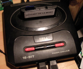 Should we return to Nintendo ? The SNES? No thanks, I want to have fun, not having to learn to code on a pseudo-16bit patchwork. This is the exact moment where I remembered that Realmyop gave me a
  Most games base their timing and reading of these buttons on the frequency of the picture rendering to the screen, at 50 or 60Hz. So we'll see pulses on SELECT 50 or 60 times per second. However, the polarity of the signal can vary, we're never sure if the game will put the signal high first, then low, or the opposite. There is no standart and I have seen both cases in commercial games (from the same developers!).
 Let's move on to the modification itself. It's likely that you have an official Sega joypad, if this is not the case, you must find which wire corresponds to the SELECT line yourself. In Sega joypads, it's simple, it is on pin 1 of the single integrated circuit (a 74HC157, quad 2-to-1 multiplexer).
 All this can easily fit on a small piece of stripboard and placed in a hollow area of the joypad. A hole may be made near the cable to place the LED if you chose to useone. It's also a good idea to keep the microcontroller on a socket, the height is not a problem and it will be practical to remove it if improperly flashed.
 The seller was kind enough to offer the 6V battery (which isn't always included and not the most common) and a small neon bulb to test the collar's electrodes.
 To get meaningful values, we must simulate the actual operating conditions by feeding the collar with the 5V that will be given by the Megadrive rather than the 6V from the battery, and also simulate the resistance of the skin with a conventional carbon resistor.
 The accuracy of the signal's trace was unfortunately limited because my probes were only capable of dividing by 10 (and not by 100). I didn't make a divider circuit with a follower just because of pure laziness... At least we now know that the positive voltage peak exceeds 200V (one can imagine the plot going up to about 400V), and that it lasts about 100 microseconds.
 The collar has its own microcontroller but I won't describe its operation (bark detection, timeout, "motion" detection...) because we already know everything we need to know.
 To connect the joypads, I used an old USB cable with data lines (not only power). As we only need 3 wires, one wire won't be connected.
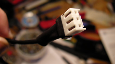 The plug is made of the female complement of the connector previously installed on the joypad. No need to use a crimp pliers here, just solder the wires to the metal pins and insert them into the plastic.
 The collars connects to each joypad. I admit that the white connector is not the best, but nothing prevents you from painting it !
 Operation is simple, the software displays a menu with 6 choices: Small shock on player 1, 2, both players, long shock on player 1, 2, both. The choice is naturally made with the up and down buttons, and validated with the A button


