Reverse-engineering infrared-based electronic shelf labels

- Why ?
- Brands and technologies
- Infrastructure
- Infrared MAC
- Infrared PHY
- Image format
- Tag electronics
- Transmitter electronics
For concrete code examples check out PrecIR on Github.
For a compatible USB IR interface check out ESL Blaster on Tindie.
Why they exist
To consumers, Electronic Shelf Label (ESL) manufacturers list a few pretexts for their existence, often phrased as benefits:
- ESLs are ecological: they can be updated and they last for years, it saves paper and ink !
This is utter bullshit. Prices and products don't change that often, and the necessary ressources to make the electronics, batteries, and plastic enclosures that constitute the tags largely outweigh what they would replace in terms of paper and ink. - ESLs provide better price accuracy, what you see is what you'll pay !
Partially true. In practice, most of the time updates are done store-wide at night. Also, the store database is still maintained manually so an important human factor remains. - The store staff spends less time changing paper labels, allowing them to dedicate more time to the customer !
I wouldn't be surprised if that was already used as an excuse to cut jobs. - Some ESLs are NFC enabled. You can tap your phone to get more infos on a product !
Seriously, of the few who know about this, who uses it ? Important infos such as allergens are mentionned on the product itself.
On the other hand, the selling points given to store chains make much more sense:
- Instant price updates. Hot day ? Raise bottled water by 20% in one click !
- A single person can manage everything. No maintenance outside of replacing the ESLs every 5 to 10 years.
- Some ESLs have LEDs to attract attention. Brands can pay to make their product more visible.
- Staff on the store floor can interrogate ESLs to see stock info. Less empty shelves !
- Get a significant advantage over smaller stores who can't afford the system.
- The whole thing pays for itself in the first few years.
Why mess with them ?
Sometimes you don't need a reason to do things. But if you really need one in this case, here are a few:
Because it's fun. Because you want a cool name tag. Because you may learn something. Because the vast majority of the tags don't have embedded anti-theft devices. Because multi-billion store chains believing in new ways to earn more but not in preserving the environment deserve it.
Mischievous acts proven to be possible:
- Change displayed prices
- Change displayed images
- Lock tags up for hours without any communication possible
Mischievous acts one could dream of:
- Drain tag batteries very quickly
- Change tag address or access keys, making the store unable to use it
- Remotely update a tag's firmware
- Remotely update all in-range tags firmware
Brands and technologies
There are many brands of ESL systems, each with their own proprietary infrastructure and software.
Free and accurate market share information is hard to come by, there's some geographical segmentation (some brands are more common in some countries) but overall there's only a few leaders. This makes it rather easy to identify brands just by memorizing how their ESLs look.
Even if it doesn't seem like a big concern, some systems are said to implement security measures.
It is not known if these are effectively in place, nor what they're supposed to prevent (unauthorized updates ? Price spying ? Both ?).
Bidirectional communication trades battery life against information reliability. ESLs that can answer allow the system to perform retries on failed updates, retrieve battery status, and even do coarse geolocation. Early systems which weren't energy efficient enough couldn't do that.
| Brand | Communication technology | Bidirectionnal communication | Security | Characteristics | Most common in | Tags appearence |
|---|---|---|---|---|---|---|
| Pricer | Proprietary high-speed infrared | Yes | No encryption whatsoever, 16-bit key with default value | Dish-like transmitters scattered across store ceiling. Segment and e-paper based tags. Black IR sensor visible on the front. | Europe, US |  |
| SES Imagotag | Proprietary 2.4GHz radio Texas Instruments CC2510 chip |
Yes | Mentionned in brochures. Chip has hardware AES-128. | Modern ESL system called "Vusion". RGB LED. | Europe, US |  |
| Altierre | Proprietary 2.4GHz radio | Unknown | Unknown | Rather old system. Tags use distinctive graphic monochrome LCDs. | Europe, US |  |
| Samsung | Zigbee 2.4GHz Radio | Yes | Unknown | - | Asia | TODO |
| Digi (Teraoka Seiko) |
Radio | Yes | Unknown | - | Europe, Asia | TODO |
| NCR | Proprietary UHF radio | Unknown | Unknown | Very old, one of the first ESL systems. Rarely found nowadays. | US | TODO |
| Hanshow | Proprietary 2.4GHz radio | Unknown | Unknown | Seems to be used in smaller installations such as convenience stores and pharmacies. | Europe, Asia, US | 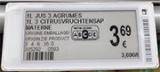 |
| ZKong | Radio | Unknown | Unknown | - | Asia |  |
| DisplayData | Proprietary 920MHz radio | Unknown | Unknown | ID barcode on the left, round edges. | US |  |
SES / Store Electronic Systems |
Proprietary LF 38kHz radio | No | None. Nothing. Really. | Radiating cable hung across store ceiling. Very slow updates. Wonky protocol. Phased out since SES bought Imagotag. | Europe |  |
| Countless noname systems from Alibaba | Probably generic 2.4GHz radio or BLE | Unknown | Unknown | More chances of being used in independent stores which don't need any uniformity in ESL systems. | - |
The following infos will focus on the only infrared system currently in existence, which is believed to occupy at least a 15% market share worldwide.
Infrastructure
The main selling point of the infrared based system is its speed and its immunity to radio interference in the cluttered 2.4GHz band.
Some years ago the two-way communication scheme was also put forward, but today the rest of the industry caught up and the feature became the norm.

Here's a funny quote from a store manager, boasting about the unique infrared technology:
“There is absolutely no way the system can be hacked or suffer interference from any other wireless devices which are powerful and mobile today. It’s the same, secure technology that was developed specifically for heat-seeking missiles fired from fighter jets.”
The infrastructure is made of a management server, one or more base stations (BS), transceivers (TRX), and of course ESLs.
The server is on the store's premises but out of sight of the public. It's hooked up via ethernet to one or more base stations, which are also generally hidden somewhere. These in turn control up to 32 infrared transceivers via RS-485, which are suspended from the store's ceiling and very recognizable.
Even with powerful infrared transmitters and sensitive receivers, optical communication can't rely much on reflections and ends up being mostly line-of-sight.
Because of this, care must be taken during setup to properly place enough TRXes to avoid any dark zones where ESLs couldn't be reached by the system.
Radio systems in the 2.4GHz band suffer to a lesser extent from the same problem.
One notable story one employee told me was about bags of dog food being great RF absorbers.
When individual tags are associated with products by store employees during setup, the data takes a long path from their handheld barcode scanner, to the WiFi acces point, to the store's network, to the ESL server, to the BS, to the TRX, to finally reach the tag.
If first learned about that thanks to an old promotional video. The employee uses a standard handheld Metrologic device to scan product barcodes and tag barcodes in pair, in order for the management server to register the association. The tags infrared replies made visible by the camera are seen transmitted with a significant delay.

Infrared PHY
Data is transmitted from the TRXes to the ESLs by bursts of 940nm infrared light.
The modulation used is Pulse Position Modulation (PPM) with proprietary parameters.
PPM codes the data in the time between pulses. Therefore, for a given number of symbols n, there's always n+1 bursts.
The bursts are fixed periods of the high frequency "carrier", which is always a 1.25MHz square signal. ESLs have a narrow passband filter which makes them blind to any signal outside approx. +/-10kHz of this frequency.
Carrier is put in quotes here because the bursts don't actually carry the data, unlike the bursts in many standard IR remote protocols do.
Because the data is encoded with time, the total transmission time obviously depends on the actual data.
It may be possible to hack around limitations of IrDA transceivers to form valid pulses, but I'm not aware of any semi-intelligent part capable of producing the required carrier frequency. Phone infrared transmitters that I've tested are limited to hundreds of kHz.
There are two known symbol sets used: a legacy, slower one, and a more recent faster one certainly created to support the higher data rates needed to update graphic ESLs in a reasonable time.
Data is always sent in bytes from first to last.
PP4
As the name implies, this set uses 4 symbols.
Each span between bursts therefore represents 2 bits.
Segment-based ESLs run off a 32768Hz crystal. To allow simple decoding and to keep power consumption low, the timing of PP4 symbols is based on that period, t = 30.52us.
Symbol durations are ordered in a way to form a 2-bit Gray code.

- Symbol 00: 2t = 61.04us
- Symbol 01: 4t = 122.07us
- Symbol 11: 6t = 183.11us
- Symbol 10: 8t = 244.14us
Bursts last a bit more than a period. 1.3t = 40us works well (50 periods of 1.25MHz).
The least significant bit pair of each byte is transmitted first.
E.g.: 0x84 (binary 1000 0100) is sent as 00, 01, 00, 10.

Public documentation mentions that PP4 can achieve bitrates of 10kbps.
Transmitting only 00's: (61.04us + 40us) / 2 = 50.5us per bit = 19.3kbps.
Transmitting only 10's: (244.14us + 40us) / 2 = 142.1us per bit = 6.9kbps.
Average: 13.1kbps.
PP16
Same idea but with 16 symbols instead of 4, encoding 4 bits per symbol.
Thanks to higher frequency crystal or the use of PLLs in graphic ESLs, the base period was also made shorter to further increase speed.
Symbol order seems random. Base period is t = 4us (-1 for each symbol ?).
The burst lasts 21us.
- Symbol 0000: 27us
- Symbol 0001: 51us
- Symbol 0010: 35us
- Symbol 0011: 43us
- Symbol 0100: 147us
- Symbol 0101: 123us
- Symbol 0110: 139us
- Symbol 0111: 131us
- Symbol 1000: 83us
- Symbol 1001: 59us
- Symbol 1010: 75us
- Symbol 1011: 67us
- Symbol 1100: 91us
- Symbol 1101: 115us
- Symbol 1110: 99us
- Symbol 1111: 107us
A special 4-byte header must precede frames transmitted in PP16: hex 00 00 00 40.
Public documentation mentions that PP16 can achieve bitrates of 38kbps.
Transmitting only 0000's: (27us + 21us) / 4 = 12us per bit = 81.4kbps.
Transmitting only 0100's: (147us + 21us) / 4 = 42us per bit = 23.3kbps.
Average: 52.35kbps.
Infrared MAC
Data is packed in frames including a header, an address, a command, one or more parameters, and a CRC.
Each tag has a unique 32-bit low level address called "PLID" (probably for Price Label ID).
Most commands require it, a few allow the use of the broadcast value of 0.

The PLID is pre-programmed in each tag and can't be modified*.
The store infrastructure is made aware of the presence of a given ESL by entering its unique ID barcode in a database.
This barcode is found on a sticker on the backside of the tag, or lasered on the front next to the display.
It is unknown if there's a broadcast command to ask a tag to return its ID barcode data, in case the barcode can't be read.
The barcode uses Code128 symbology, and is made of 17 alphanumeric characters.

Several criteria must be met for the data to be valid:
- The second character must be a '4'
- Manufacturing unit must be under 64
- Manufacturing week must be under 54
- The serial number must be under 65535 (must fit in 16 bits)
- The checksum is the sum of the ASCII values of the previous 16 characters, modulo 10 (the last digit).
For example, G4591371776312423 decodes to:
Tag made by unit 59 in the 37th week of 2001, serial number 17763, tag model code (1)1242, checksum 3 (valid).
The tag's PLID is derived from the ID barcode data. It's divided in two 16-bit words.
The upper one corresponds to the MMYWW fields, the lower one to the SSSSS field.
The example above shows 59137 and
17763, giving a PLID of hex 0xE7014563.
From now on, byte values will be given in hex.
The basic structure of a frame is:
[VER] [PLID] [COMMAND] [PARAMETERS] [KEY] [CRC]
- VER is a byte indicating the protocol version code. Segment ESLs understand code 0x84, graphic ESLs 0x85.
- PLID: The 32-bit PLID described above, least significant byte first. The above example would give 63 45 01 E7.
- COMMAND: A 7-bit command code and an acknowledge request flag. The ack flag is bit 7.
- PARAMETERS: One or several parameters, depending on the command.
- KEY: The 16-bit store key, which has very high chances of being 0.
- CRC: A 16-bit CRC computed over all the previous bytes starting from the protocol version code.
Both the initial value and the polynomial are 0x8408.
Frames with invalid lengths or CRCs are ignored.
Segment page change command
84 [PLID] AB xx [KEY] [CRC16]
Protocol code 4, ack request enabled. 0x80 + 0x04 = 0x84.
The page change command is broadcast, so the PLID is set to 0.
AB is the change page command.
The xx parameter byte is formed as follows:
SPPPPTTT
S: If set, makes the page become the default one.
P: Page number, 0 to 15. Pages 0 to 7 can be customized. Pages 8 and above are used to report ESL internal infos.
T: Duration of display.If S is set, this is ignored. Durations are 4s, 8s, 30s, 480s (8min), 1800s (30min), 3600s (1 hour), 5400s (1h30).
Example: 84 00 00 00 00 AB 11 00 00 A5 E4
Asks tags to show their page 2 during 4 seconds.
Graphic ESL ping / wake up command
85 [PLID] 17 01 [KEY] [PAYLOAD] [CRC16]
ESL spend most of their time asleep, only checking periodically if they're receiving infrared data.
It may be necessary to send wake up frames in loop for up to 4 seconds in order to get the ESL's full attention.
The purpose of the parameter byte is unknown.
It seems that the payload of this type of frame can be anything as long as it's 23 bytes long and starts with a 0 byte.
Segment update command
84 [PLID] 3A xx [KEY] [DATA] [CRC] 00 00 09 00 yy 00 00 [CRC16]
This is an addressed command. Broadcast doesn't work (unfortunately).
The segment data [DATA] is 23 bytes long, meaning that a maximum of 23 * 8 bits = 184 segments can be controlled.
The mapping of bits to segments varies depending on the ESL's model, which is kind of a pain in the ass. A set bit turns the segment on.
xx: Page number to udpate (0 to 7 << 3)
CRC: CRC16 of the [DATA] only (might be ignored ?)
00 00 09 00: Unknown (can be all 0 ?)
yy: Flash page number << 4
Segment blink update command
84 [PLID] 3A xx [KEY] [DATA] [CRC] cc cc 00 00 yz 00 00 [CRC16]
This is an addressed command.
A subcommand of the "segment update" command used to set a mask to define which segments must blink.
As above, the segment data [DATA] is 23 bytes long.
xx: Page number to udpate (0 to 7 << 3) OR 80
CRC: CRC16 of the [DATA] only (might be ignored ?)
y: Blink on time (4 bits. 0 is fast, F is slow)
z: Blink off time
(same as above)
Image update command
Updating a graphic ESL's display requires many frames transmitted in a precise order, it's quite an involved process.
If any of the frames is invalid or not received properly, or if the image doesn't fit on the display, the update will fail.
The ESL must first be waken up with the above wake up frame transmitted for a few seconds.
First is a parameter frame describing the image and the format of the data to come next:
85 [PLID] 34 00 00 00 05 [LENGTH] 00 [TYPE] [PAGE] [WIDTH] [HEIGHT] [XPOS] [YPOS] [KEY] 88 00 00 00 00 00 00 [CRC16]
LENGTH: Word. Length of the image data in bytes
TYPE: Byte. Image data compression type. 0 is no compression, 2 is bitwise RLE (see below).
WIDTH, HEIGHT: Words. Size of the image in pixels.
XPOS, YPOS: Words. Position of the image in pixels from the top left corner of the display.
One or more data frames follow:
85 [PLID] 34 00 00 00 20 [INDEX] [DATA] [CRC16]
INDEX: The data frame's index. Starts from 0 and increments every frame.
DATA: Image data. Maximum 20 bytes per frame. Format depends on the TYPE parameter above. See below for encoding.
After the last data frame, a final update frame is sent:
85 [PLID] 34 00 00 00 01 [PAYLOAD] [CRC16]
PAYLOAD: 22 zero bytes. Value may not matter.
After this last frame, the ESL may take a few seconds to react and update its display. I have a few tired ones that take up to 10 seconds.
Image format
There are two known image formats: raw and RLE compressed.
Black and white ESLs use a single block of binary data. 0 means black, 1 means white.
Black, white and red ESLs use two blocks of data. The first one represents black and white pixels, the second forms a mask with 0 meaning red.
Newer 4-color ESLs may use two blocks as real bitplanes, but this is not confirmed.
Image encoding is always done from the top left corner to the bottom right
The raw format is type 0. Each pixel is encoded in a bit. If necessary, padding is done with zeroes.
The RLE format is type 2. Instead of dedicating one bit for each pixel, the length of continuous runs of identical pixels are encoded.
To further reduce the data size, the length of the counts is variable and unary coded.
The first bit of an RLE bitstream represents the very first pixel's color.
Then follows a list of lengths coded as such:
[n-1 * 0 bits] [length coded in n bits]
For example, if the image starts with 13 white pixels, then 59 black pixels, the bitstream would be:
1 000 1101 00000 111011
- 1: First pixel is white
- 000: Next length value will be 4 bits long
- 1100: 12 white pixels
- 00000: Next length value will be 6 bits long
- 111011: 59 black pixels
- And so on...
It's enterily possible that an image compressed with this scheme will end up larger than if it wasn't compressed.
This will often happen with heavily dithered images, because of the many changes in pixel colors causing lots of length coding overhead.
Tag electronics
TODO: Translate
Il existe deux types principaux:
- Les ESL à segments. Économes en énergie, moins chères, mais seulement capables d'afficher quelques caractères.
- Les ESL graphiques. Basées sur des écrans e-paper, bien plus chères, mais permettent d'afficher tout et n'importe quoi.
Ces deux types partagent une base commune: un ASIC mixed-signal (analogique et numérique) propriétaire qui s'occupe de la communication infrarouge au plus bas niveau, et qui abrite également un microcontroleur et de la RAM.
Grâce à Deus Ex Silicium, il a été possible d'observer de près cet ASIC. Il a d'ailleurs publié une vidéo à ce sujet:
Il m'a également fourni plusieurs photos du die, qui ont pu être fusionnées pour produire une photo plus grande.
La finesse de gravure et la complexité du microcontroleur, même sur un circuit conçu pour être le moins cher possible, ne permet pas de discerner individuellement les transistors. Cependant on peut très bien voir les différents blocs:

Il y a deux zones de RAM distinctes, la plus petite sert de RAM de travail pour le MCU. Si on se réfère aux lignes et aux colonnes, celle-ci ne ferait que 32 ou 64 octets. L'architecture du microcontroleur est inconnue. Vu la surface utilisee, je suspecte du 8 bits plutot que du 4.
La logique pour le pilotage des sorties LCD semble être mélangée avec celle du MCU, il n'y a pas de bloc distinct à part les 4 rails d'alimentation qui suivent le bord.
Le bloc PM (Power Management) / Analogique contient de nombreux condensateurs, qui apparaissent comme de gros rectangles de couleur unie. Ce bloc s'occupe de la génération des tensions pour le LCD ainsi que l'amplification et le filtrage du signal provenant de la photodiode.
Le point remarquable est qu'il n'y a pas l'ombre d'un bloc de mémoire flash. Je vois trois raisons possibles à cela:
- Il faut relativement beaucoup de courant pour effacer et programmer de la flash
- Il faut un process special pour avoir de la flash sur un die, qui dit process special dit plus cher
- Le fait que la RAM soit volatile est peut être un avantage financier
Comme il n'y a pas d'autre bloc de mémoire, le firmware est forcément dans le gros bloc de RAM.
Si l'ESL perd son alimentation, non seulement les données affichées s'envolent mais le firmware aussi.
En clair, quand les piles sont mortes ou retirées pendant trop longtemps, il n'y a aucun moyen de ressusciter l'ESL.
Le chargement initial du firmware se fait certainement en usine via des contacts qui se trouvent au dos de la carte. Ils sont ensuite masques par une etiquette mais ils toujours accessibles à travers le boitier si on la retire (voir plus bas).
Restriction pour contrôler le recyclage et garder la main sur les étiquettes ? Simple dommage collatéral lié à l'utilisation de RAM pour faire des économies de quantité ? A vous d'en juger.


Basés à Hong Kong, Solomon-Systech sont relativement connus pour leurs très courants controleurs LCD (SSDxxxx). Ils proposent un service de design d'ASIC et ont leur propre ligne de microcontroleurs (dont ils ne parlent plus sur leur site aujourd'hui).
Les premieres etiquettes graphique de la marque couplaient un ASIC avec un MCU ATMega168 et une EEPROM série pour stocker les images des différentes pages. Cet ASIC joue simplement le role de recepteur/emetteur IR puis passe les donnees au MCU externe qui fait le gros du travail.
J'ai aussi ouvert l'ASIC d'une des étiquettes graphiques (avec des degats). La zone en damier semble être une couche de distribution d'alimentation ou d'égalisation de surface au dessus de la logique. Une partie des blocs analogiques est toujours visible.

En comparant avec le die de l'ESL à segments, on peut remarquer de nettes ressemblances.

On peut aussi voir le gros transistor pour la LED infrarouge.
Derrière un autocollant se trouvent deux petits trous dans la coque de l'ESL donnant sur des pastilles du PCB. L'une va au plan de masse, l'autre à l'ASIC. Des impacts de pointes sont visibles, indiquant que ce sont soit des points tests pour vérifier que l'ESL est vivante en sortie d'usine, soit une interface série pour charger le firmware et leur code unique.
Le fait que des trous aient été prévus dans la coque laisse penser que le chargement du firmware peut se faire à nouveau.
Note: C'est pas du 1-wire, c'est vérifié. Ca aurait été surprenant: il aurait fallu qu'ils paient pour utiliser la technologie. C'est probablement un protocole unidirectionnel très simple, pour éviter d'utiliser trop de surface dans l'ASIC. J'imagine bien un gros registre à décalage. Je ne crois pas en l'existence d'un bootloader puisqu'il s'effacerait avec le firmware.
Balancer une horloge sur un contact et du bruit binaire sur l'autre brique l'ESL !


Le quartz est taillé pour 32768Hz, et sert dès la mise sous tension de l'étiquette (>2.2V).
A droite on trouve la photodiode D1 wire-bondée directement sur la carte, la LED infrarouge de réponse D2 au dessus, ainsi que son condensateur réservoir C4.
Une charge pump intégrée dans l'ASIC génère du 6V sur TP9, probablement pour l'afficheur.
Un procédé nomme "precharge" géré par l'infrastructure permet a l'étiquette de recharger C4 entre plusieurs réponses (allant jusqu'a 2 secondes) afin d'obtenir une réponse puissante malgré le peu de courant disponible instantanément avec les piles CR2032.
TP13: Tension piles (3V).
TP18: Masse.
A noter: 3 fins de pistes sans vernis sont visibles à gauche de R2, possiblement une interface de programmation ou de debug propriétaire.
Todo...


Toujours les trous pour la programmation en usine (étiquette retirée). Fixme: le trou à gauche est utilisé.

Tiroir contenant les deux piles CR2032. Il est soudé !

Surprise à l'ouverture: un autocollant sans contact collé derrière l'écran. C'est clairement du NFC, pas un bête antivol 8.2MHz.
Le fait qu'il n'y ait pas de connection electrique entre l'autocollant et la carte indique qu'il n'est pas possible de mettre à jour son contenu par infrarouge.

TP12_B: Prog ?
TP21_B: VBatt
TP18_B: GND
More recents tags have a single QFN asic - TODO: Picture.
Transmitter electronics
TODO: Add more details, translate.
Uses a Hitachi H8/3687 MCU to decode RS-485 messages and a Lattice 4064V CPLD to generate the IR signal with precise timings.
A fast enough microcontroller and careful programming would work but they might have chosen a CPLD to future proof eventual protocol updates.
It is unknown if the CPLD can be reprogrammed by the MCU.
Given the very low amount of logic blocks in the CPLD, it probably just acts as a dual presettable timer to generate the IR symbols from burst and pause durations provided via a parallel bus by the MCU. It should also form a prescaler to do 10MHz / 8 = 1.25MHz.
Patent: WO0209322
These can be daisy-chained up to a certain number. RJ45 connectors but not Ethernet. Unsure why they didn't use PoE.
RS-485 and 48V power supply. MCU runs at 20MHz and feeds the CPLD with 10MHz.
The uplink circuit is interesting. It has to be extremely sensitive to detect the short and potentially weak IR blinks from the ESLs.
They actually used components made for FM radio !
SA636 FM IF chip. An AD9833 is used to generate the LO at ?? MHz. A 455kHz discriminator is used.
La porteuse de reponse est a 1.245MHz. Decalage de seulement 5kHz du 1.25MHz du downlink ?
Filtre ceramique, logo Murata marquage XH:

On trouve une connexion UART 38400bps sur l'µC, qui semble etre unidirectionelle:
***** TRX INIT *****
Firmware:
Compile date: Feb  4 2007
Compile time: 20:39:15
PON Counter:0001
TCSRWD:AA
WOKE UP FROM POWER ON
WATCHDOG INITIATION STARTED!
WATCHDOG INITIATION COMPLETED!
irrxSetup:
 Intg. Time:02E1
 Noise Time:02C2
 PreFB Time:0DD8
 RIM Time  :1F95
CABLE: TxError
CABLE: RxError
CABLE: 48V Error
FELIF: Closed (HW error)
Hello: 0000632F
Hello: 0000C651
Hello: 00012BCD
L'µC detecte la presence du 48V avec un pont diviseur directement sur l'alimentation (avant la diode): 100k et 4.7k, donnant 2.15V sur une broche ADC (ref interne + comparateur certainement). En ajoutant 100k en parallele sur la resistance de 100k deja presente (=50k), et en alimentant en 30V seulement, l'erreur disparait.
TxError et RxError semblent etre liees a une mesure electrique, et pas un echange de donnees (rien sur la liaison RS485 au demarrage).
FELIF closed ? J'espere que c'est lie a l'absence de 48V...

There's LED chain fault detection.


