Cette page a au moins 14 ans ! This page is at least 14 years old !
This article covers a way to add some sort of MIDI
input to the Kaossilator by tricking it to read generated voltages
instead of those coming from the touch pad.
Please excuse any English mistakes, everything was
written in a rush and not even spell-checked. The text will be reviewed
and modified later to add more details and to correct eventual errors.
I know the Kaossilator Pro has stock MIDI in/out capabilities,
but did you see the price difference ?
Harvesting informations
I guess there's no need to present the Kaossilator,
if you're reading this then you probably know what it is and what
it does already. Getting to the internals is very simple, it's just
a matter of a taking out a few screws and an inefficient "warranty
voiding" sticker.
The touch pad is of a simple resistive type, which
is probed at 500Hz by the Kaossilator's microcontroller.
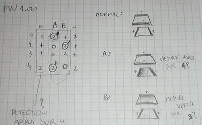
The touch position is normally read by generating
a "voltage gradient" on one layer of the touch pad, and
measuring the resulting voltage on the opposite one. The two layers,
when in contact, act as a voltage divider.
The Kaossilator seems to execute its position reading
routine even if no push was detected.
The pad has 4 connections, which I labelled according
to their position on the PCB's plug.
Their relation to the positions can easily be guessed by shorting
or tracing out the connections:
1: Top (Upper layer)
2: Right (Lower layer)
3: Left (Lower layer)
4: Bottom (Upper layer)
The reading routine runs like this:
Both lines 2 and 3 are held high when the pad
isn't read. This puts all of the lower layer at 3.3V. Lines
1 and 4 are set to a high-impedance state.
When a read occurs, the 4th line is first checked.
If the voltage on it exceeds a certain threshold, a press is registered
(the voltage varies a bit with the amount of pressure).
Then, the 2nd line is set to ground, putting
3.3V across the lower layer. The voltage on the 4th line
is read again to get the horizontal position.
Lines 2 and 3 are then set to a high-impedance
state, to now use the lower layer as the probe. Line 1 is set
to 3.3V and line 4 to ground. The vertical position is read on
line 2.
As you may have noticed, the measurable voltages
always appear on two different lines at the same time (1 and 4 for
horizontal, 2 and 3 for vertical), but the circuit is only able
to read lines 2 and 4.
Sampling doesn't seem to be made accross the entire
measuring period. However, the voltage has to be stable in less
than 30µs (the lines are set for 60µs).
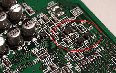
The touchpad reading circuit can
be found below the LED display on the front side of the PCB.
It's formed of two npn transistors connected to
lines 1 and 3.
This is consistent with the fact that those two lines only have
to be high or floating.
An unidentified IC seems to be housing a few more
transistors for line 2 (which can be high, low, or hi-Z) and line
4 (which have to be low or hi-Z). Those two lines are also obviously
connected to the Kaossilator's µC through RC low pass filters.
No way to have access to anything digital regarding
the touch pad from here... So analog is the only way. (unless someone
finds a compatible flash µC, guesses the DSP's protocol, and
writes a new firmware... Anyone up for that ?).
I didn't want to use any DAC IC since they may be
sometimes hard to find, and the only one I had (a MAX518) needed
a 5V power supply.
Given the number of possible voltages which would
have to be generated and the limited space, a double 8-bit R/2R
DAC didn't seem like the right solution.... The remaining choice
was filtered-PWM DACs, which would only take a pair or capacitors
and resistors.
The main drawback of this type of DAC is the settling
time. The capacitors have to be chosen to smooth out the voltage,
and also allow it to settle fast enough so that the Kaossilator
won't sample the voltage right in the middle of the charging curve.
At 12MHz, the max PWM frequency is 12MHz/256 = ~47kHz.
(The ATTiny2313 had difficulties to run at 16MHz on the Kaossilator's
3.3V supply).
It might be possible to use the ATTiny26's high-speed
PWM to solve this problem, but they're getting obsolete...
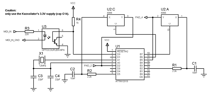
Building the circuit
(Click for full size)
The ATTiny2313 microcontroller was chosen as a base
for the circuit because it's cheap, has an hardware UART, two separate
PWM outputs, and enough I/O pins. Because of the voltage settling
time being way over 50µs, half of a CD4066 (quad analog switch)
is used to gate the DACs outputs, making the Kaossilator think the
voltages are coming from the touch pad. This allows the voltages
to stabilize when reading doesn't take place (500Hz gives a bit
less than 2ms).
An optocoupler is used for the MIDI input as usual
(current loop).
Line 2 (horizontal reading) is connected to the
OCRA's DAC, while line 4 (vertical reading) is connected to the
OCRB one. Line 2 is also connected to the INT0 pin to trigger an
interrupt when the Kaossilator initiates a read. The DACs are always
on and their output is changed as soon as the right MIDI message
is received.
Line 4 is also connected to a pin configured as
a digital high output, to simulate presses in between readings.
It is set to hi-Z when reading occurs.
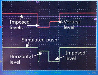
Line 2 (red) and line 4 (yellow).
The original touch pad can be left connected to "bend"
the note, or to use it normally when the MIDI translator isn't on
(not shown in the video).
The low pulse just before the horizontal level gets
out of the CD4066 on line 4 is intentional, it allows to "discharge"
the touch pad (it has a rather high capacitance). It has no effect
since the Kaossilator only reads the value mid-pulse.
Total reading lasts about 120µs. The horizontal
value and vertical values are respectively picked up 30µs
and 90µs after the falling edge of line 2.
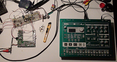
MIDI testing setup with an EA-1 as controller.
The AVR only understands the "note on",
"note off", and NRPN change commands. The MIDI channel
and NRPN numbers are hardcoded, as a dedicated interface to change
them isn't in the scope of the project for now...
A lookup table containing the right values for the
PWM generators can be used to map each MIDI note to a specific voltage
that has to be generated in order to produce it the Kaossilator.
Since it can only reproduce 2 octaves at once (24 notes on the horizontal
axis), the LUT can only be 24 bytes long. Other MIDI notes values
can be wrapped or just ignored.
As many audio equipment manufacturers do, Korg freely
gives out the MIDI implementation of each of their devices. The
one for the EA-1 is here.
Download the C source for AVRStudio
4 (ugly but commented).