For front-loader consoles, for kits revision F only.
You will need:
These instructions assume that the console will be seen from up top, and orientated so that the controller ports point towards you.
 Make sure that the console is in working order, power it up and check that you can reach the CD menu and that there's no CD in the drive. It doesn't matter if CDs can be read or not.
Turn off the console and unplug all cables attached.

Flip the console over. You may want to place it on a soft surface like cloth or bubble wrap to avoid scratching the top shell.
Remove all 7 screws as shown.

Flip the console back the right way around and gently raise the top shell.
Unplug the wire bundle going to the power button by pulling on the connector located on the small board.

Remove the 16 screws holding down the metal shields. There's a large one over the CD drive, and a smaller one over the auxiliary board.
Lift them and put them aside.

Remove the 4 screws holding down the CD drive. They're located in deep holes.
Unscrew the grounding wire going from the CD drive to the metal beam.
This particular screw has a different thread pitch than the others, remember this for reassembly.

Unplug the CD drive's white flex cable from the right of the console's main board, by pulling it straight up.

Lift the CD drive and put it aside.
Also remove the metal shielding that was underneath it.
The main board should now be exposed.

Disconnect the thick power cable bundle connected to the main board by squeezing the connector and pulling on it.
Disconnect the remaining smaller wire bundles by pulling on them. There's two on the left, and one on the right.

Unscrew the metal beam and lift it to remove the auxiliary board.
THIS STEP IS ONLY REQUIRED IF YOU WANT TO KEEP THE CD DRIVE OPERATIONAL.
On the right of the console's main board, locate the white 10-pin connector marked "CN6". You can either desolder it or keep it in place. Removing it will allow you to use shorter wires.

Cut three lengths of approx. 10cm (4 in) or 16cm (6.5 in) of wire depending on your previous choice. Strip approx. 2mm off both ends.
The provided wire has multiple strands for better flexibility. Twist the strands tightly together and tin them. Make sure no strand is poking out of the tinned bundle.

Solder the wires in place of the connector, or you chose to keep it, to its pads on the underside of the console's main board. The wires must be soldered to the rightmost 3 pins.
Leave the 3 wires floating for later. Be careful not to pull on them.
 On the main board, locate the 40-pin ROM chip marked "FRONT-SP1" near the center.
 This is the delicate part:
With sharp, flush cutting pliers, cut pin 12 just above the board.
Be very careful not to scratch the board with the pliers tips.

Bend the pin from the chip so it sticks out horizontally.
Avoid bending back and forth, as it may snap from the chip easily.
Cut two lengths of approx. 10cm (4 in) of wire. Strip approx. 2mm off both ends.
The provided wire has multiple strands for better flexibility. Twist the strands tightly together and tin them. Make sure no strand is poking out of the tinned bundle.

Solder a wire to the lifted pin, and another one to the pad on the board where the pin was soldered.
Make sure that both solder joints aren't touching. Leave the two wires floating for later.
Be careful not to pull on them.

Put the auxiliary board and the metal beam back, screw them back in place but don't reconnect the wire bundles right now.

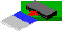
Insert the provided flex cable in the loader board's connector.
Slide it in with the blue tab facing up, contacts facing down.
Use your fingernail or a flat screwdriver to help if needed, but be careful not to poke or cut through it.
It should go in 2~3mm. Make sure it's in straight.

Plug the 10-wire connector coming from the auxiliary board to the CDDA pins on the loader the right way around: the differently colored wire (often brown) must go on the side indicated by a small white arrow.
The connector should fit in just right with a bit of force. Be careful not to bend the pins.

Locate the square chip having a marking containing "68HC000" around the bottom right of the console's main board, and check how it is oriented by looking for a small dimple on one of its edges.
It should match the text orientation, being on top of it.

Orient the loader board the same way the chip is by matching the white arrow printed underneath with the edge that has the dimple.

Align the loader's square connector on top and press firmly at the center to plug the board over the chip. It won't make a very audible click but you should feel it locking into place.
Make sure that the board is firmly connected and that it is parallel to the main board. There should be no gap between the loader's connector and the board.

Solder the two wires coming from the FRONT-SP1 chip to the loader as follow:
The pad wire must go to the A pad on the loader.
The lifted pin wire must go to the B pad on the loader.
Make sure they aren't swapped !

THIS STEP IS ONLY REQUIRED IF YOU WANT TO KEEP THE CD DRIVE OPERATIONAL.
Solder the 3 wires coming from the CN6 connector to the X, Y and Z pads of the loader board as shown.
Make sure they aren't swapped either !
![]() Place the CD drive shielding back, make absolutely sure that it doesn't touch any exposed parts or solder points on the loader, especially the A and B pads where the wires were soldered.
Place the CD drive shielding back, make absolutely sure that it doesn't touch any exposed parts or solder points on the loader, especially the A and B pads where the wires were soldered.
The shielding should only go over the white area of the loader board.
Re-connect all three wire bundles from the auxiliary board to the main board: the two on the left, and the power one on the right.
 Plug the flex cable coming from the loader in the slot board.
As before, slide it in with the blue tab facing up, contacts facing down.
Use your fingernail or a flat screwdriver to help if needed, but be careful not to poke or cut through it. It should go in 2~3mm. Make sure it's in straight.

The shiny metallic part near the edge of the slot board is the microSD card slot.
Lay the slot board on the lower right edge of the shielding, with the microSD slot to the left. The two holes on the right must align with the two holes in the shielding.
Use a single screw in the rightmost hole to keep it in place for now.

Place the CD drive back with its 4 screws. Screw the grounding wire back to the metal beam.
Don't forgot to plug the CD drive flex cable back on the main board.
Place the shielding back over the CD drive. The bend of the flex cable should fit in the free space nicely.
Screw everything back up.
Make sure that 7 screws are left over, and that all wires and flex cables are connected.
Place the top shell back over everything, and screw it back on.
Place the provided sticker wherever you please.
The installation is now complete ! VICTOLY !
Before powering up the console, you need to prepare your SD card. Please move on to this page.