For top-loader consoles, for kits revision E only.
You will need:
These instructions assume that the console will be seen from up top, and orientated so that the controller ports point towards you.
 Unplug all cables attached. Make sure that there's no CD in place.
 Flip the console over. You may want to place it on a soft surface like cloth or bubble wrap to avoid scratching the top of the shell.
Remove the screws from all 4 corners.

Flip the console back the right way around and gently rotate the top shell to your left side.
Be careful with the white flex cable connecting both halves.
Unplug the flex cable from the bottom part by pulling it straight out.
Avoid pulling it sideways, the contacts are fragile.
Leave the top part of the console aside for now.

On the bottom part, you will see two wide orange boards.
The one in front with the controller ports is called the CDD board.
The one behind with the A/V and power connectors is called the CDA board.
They should be connected to each other with a long yellow wire, which you can unplug from the CDD board.

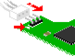
Disconnect the thick power cables going from the CDA board to the main board by squeezing the connector on the main board side and pulling on it.
Disconnect the remaining wire bundles by pulling on them. The removable side with small white connectors is on the main board, not on the CDA board !
Unplug the flex cable going from the main board to the CDD board by pulling it straight out.
Both sides are removable but removing it from the main board side will make things easier.

Remove the screws holding the CDA and CDD boards, and lift them up.
On some models, there are plastic spacers beneath the CDD board, don't lose them !
Put both boards aside.
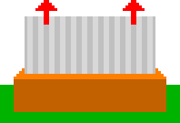
 Remove the remaining screws holding the shielding in place.
Lift the shielding and put it aside.
THIS STEP IS ONLY REQUIRED IF YOU WANT TO KEEP THE CD DRIVE OPERATIONAL.
On the top left of the console's main board, locate the white 3-pin connector marked "CN3". You can either desolder it or keep it in place. Removing it will allow you to use shorter wires.

Cut three lengths of approx. 10cm (4 in) or 16cm (6.5 in) of wire depending on your previous choice. Strip approx. 2mm off both ends.
The provided wire has multiple strands for better flexibility. Twist the strands tightly together and tin them. Make sure no strand is poking out of the tinned bundle.
Solder the 3 wires in place of the connector, or to its 3 pads on the underside of the board if you chose to keep it.
Leave the 3 wires floating for later. Be careful not to pull on them.

On the main board, locate the 40-pin ROM chip marked "TOP-SP1" near the bottom left corner.
It may also be marked "TOP-SP1 2" or "TOP-SP1 3".

This is the delicate part:
With a soldering iron, heat up pin 12 for a few seconds and carefully lift it from the board with the needle.
It shouldn't require much force. Don't pull too hard on it or you might tear the pad from the board.
 Bend back the pin over the body of the chip.
Avoid at all costs bending it back and forth repeatedly as it will easily break off.
Cut two lengths of approx. 10cm (4 in) of wire. Strip approx. 2mm off both ends.
The provided wire has multiple strands for better flexibility. Twist the strands tightly together and tin them. Make sure no strand is poking out of the tinned bundle.

Solder a wire to the lifted pin, and another one to the pad where the pin was previously soldered.
Make sure that both solder joints aren't touching, and bring the wires together to make them go in the same direction.

Secure the wires with tape or hot glue applied to the body of the ROM chip. Avoid applying glue on the pins or the solder points.
Leave the two wires floating for later. Be careful not to pull on them.

Insert the provided flex cable in the loader board connector.
Slide it in with the blue tab facing up, contacts facing down.
Use your fingernail or a flat screwdriver to help if needed, but be careful not to poke or cut through it.
It should go in 2~3mm. Make sure it is straight.

Locate the square chip having a marking containing "68HC000" around the center of the console's main board, and check how it is oriented by looking for a small dimple on one of its edges.
It should match the text orientation, being on top of it.
The orientation depends your console's version, it may point up or right.

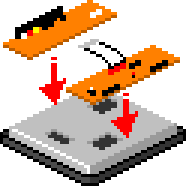
Orient the loader board the same way the chip is by matching the white arrow printed underneath with the edge that has the dimple.

Align the loader's square connector on top and press firmly at the center to plug the board over the chip. It won't make a very audible click but you should feel it locking into place.
Make sure that the board is firmly connected and that it is parallel to the main board. There should be no gap between the loader's connector and the board.

Solder the main board pad wire to the A pad on the loader board.
Solder the lifted pin wire to the B pad on the loader board.
Make sure they aren't swapped !

THIS STEP IS ONLY REQUIRED IF YOU WANT TO KEEP THE CD DRIVE OPERATIONAL.
Solder the 3 wires coming from the CN3 connector to the X, Y and Z pads of the loader board as shown.
Make sure they aren't swapped either !

Fold the flex cable according to the illustration, depending on the orientation you had to use.

Do not mark the folds too much as repeated folding and unfolding during adjustments may break the flex cable.
Leave a slight curve.

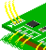
On the previously removed CDA board, locate the 3-wire bundle for CD Digital Audio (CDDA).
There are two versions of the CDA board: one has only one 3-wire bundle, the other has two.
In that case, the leftmost is the one to use.
Pass the CDDA wires through the matching opening in the shield, and plug the connector to the CDDA pins on the loader board the right way around.
The differently colored wire (often white) must go on the side indicated by a small white arrow.
On some models of the console, the CDDA wires may be too short to be plugged directly into the loader.
In this case, solder 3 lengths of wire from the CDDA connector pads on the CDA board to the unpopulated CDDA connector on the other end of the loader board.
Make sure that the order of the wires matches the order of the original wire bundle !

If a foam pad was provided and your console has a metallic shielding:
Peel off the paper backing from the foam pad and stick it on the underside of the shielding, so that it will press on top of the loader board where the 68000 chip is when placed over it.

Pass the loader's flex cable through the matching opening in the shield, and place the shield back over the main board.
Screw the shield back in place.
![]() Make absolutely sure that the bare shield does NOT touch the loader board and any of its components or exposed wires. Only the foam pad should make contact with the board.
Make absolutely sure that the bare shield does NOT touch the loader board and any of its components or exposed wires. Only the foam pad should make contact with the board.
If the proximity makes you nervous, you can stick a few strips of tape next to the foam pad to provide electrical insulation.
At this point, you can chose to test the kit without putting everything back together.
If you're feeling confident and chose not to, just continue following this guide.
Set the CDD board (with its spacers if there were any) and CDA board back on top. There are alignment posts on the shield to help placing them.
Reconnect the remaining CDA board wires and the CDD board flex cable to the main board.
The following instructions are valid only if you wish to remove the CD drive.
If that's the case, your kit should contain a black triangle board.
If you want to keep the CD drive operational, see below.

Bend back the small board connected to the triangular board approx. 45°. It requires some force. Avoid bending it back and forth multiple times as it can break the connections.
Do not press on the metallic SD card slot, !
The angle may need some adjustment depending on your preference later on.

Remove the CD drive and the board from the top shell by removing the 8 screws as shown. Keep the CD drive's 4 flanged screws aside.
Lift both parts, the CD drive may need some sligth wiggling to slide off the plastic posts.
If the CD drive and its board are still in working order, store them in a safe, dry place if you plan to use them again in the future.
Avoid touching the blue-tinted lens with bare fingers.

Try placing the triangular board in place of the CD drive on 3 of the 4 plastic posts, as shown.
The previously bent board with the SD card slot must go through the opening in the shell.
If it collides with the top CD plater under the CD lid, either adjust the small board's angle, or remove the CD plater using a flat screwdriver.

Bring both halves of the console close to each other.
Connect the end of the flex cable sticking through the shield to the triangular board in the same way you connected it to the loader board: blue tab facing up, contacts facing down.

If you want to, you can replace the console's red LED by the loader's status LED.
To do so, disable the slot board's LED by opening the JP1 solder jumper under the triangular board.
Wire a 5mm common-anode RGB LED (not included) to the CA, R, G and B pads.
Remove the red LED from the CDD board and stick the new one in place in the top shell.
The following instructions are valid only if you wish to keep the CD drive.
If that's the case, your kit should contain an assembly made of two narrow green boards (slot assembly).
If you want to remove the CD drive, see above.

The shiny metallic part at the narrowest edge of the slot assembly is the microSD card slot.
Carefully bend the slot board assembly slightly over 45° where the row of pins is.
Avoid bending it back and forth multiple times as it can break the connections.

On the top half of the console, locate the green board right next to the CD drive.
Of the 4 screws holding the board in place, remove only the top left one.

Place the kit's slot assembly over it with the bent part facing down. Align the screw hole with the large one on the assembly.
A plastic post should poke through the smaller hole to help with alignment. The bent part of the assembly should lightly press against the plastic shell.
 This should make the microSD card slot align with one of the cavities creating the vent holes.
You should be able to insert a microSD card from the other side.

Put the screw back to secure the slot assembly in place.
A wire with a crimp ring attached to the CD drive may have come loose when the screw was removed. If so, be sure to put it back between the shell's plastic post and the CD drive board so that it's pressed between them.

If your console uses a brown shield, you will have to partially cut off one of the nibs as shown on the illustration.
Use cutting pliers to remove the tip of it. No need to remove the whole protrusion.

Bring both halves of the console close to each other.
Connect the end of the flex cable sticking through the shield to the narrow board in the same way you connected it to the loader board: blue tab facing up, contacts facing down.

If you want to, you can replace the console's red LED by the loader's status LED.
To do so, disable the slot assembly's LED by opening the JP1 solder jumper under it.
Wire a 5mm common-anode RGB LED (not included) to the CA, R, G and B pads.
Remove the red LED from the CDD board and stick the new one in place in the top shell.

Make sure no screws are left over, and that all wires and flex cables are connected. Don't forget to plug back the long yellow wire between the CDA and CDD boards.
Place the top shell back over everything, and screw it back on.

Place the provided sticker wherever you please.
The installation is now complete ! VICTOLY !
Before powering up the console, you need to prepare your SD card. Please move on to this page.